This section describes the various means provided to define your device groups for each StayLinked server. All StayLinked clients that request a session through a server are assigned to a device group by that server. The device group contains many of the vital settings and attributes that control the way a connected device will interact with a telnet host and how it will be handled by the StayLinked server.
Multiple device groups can be defined for each server, but all servers will always have at least a ‘Default Device Group’. Initially, all devices that connect to the server are assigned to the default group. You can configure the attributes for the default device group, but it cannot be deleted.
You can also create and manage ‘Specific Device Groups’. Specific device groups allow you to manage device configuration information for express subsets of devices. Device groups are defined to control devices within a specific range of IP addresses and for specific device types within that IP range. When each device initiates its connection request, it is assigned to a particular device group based on its local IP address and device type. The device will be assigned to, and use the attributes of, the device group that most closely matches the device’s IP address and device type. If the device is not assigned to one of the specific device groups, then the device will be assigned to, and inherit the attributes of the Default Device Group.
Managing Device Groups
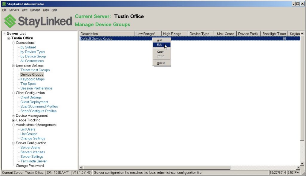
When you select Device Groups from the server tree or the Manage menu, the Device Groups list will appear in the main display panel. The Device Groups information can be sorted into ascending or descending order by clicking on any of the column headers. The currently sorted column will be indicated by an asterisk (*). Each StayLinked server will have a Default Device Group and you can add other, more specific device groups as required. Clicking the right mouse button on a device group will pop up a context menu with options to Add, Edit, Copy, Paste or Delete a group.
Maintaining Device Group Settings
When you add, edit, or copy a device group, the following window will appear that shows the current device group settings and allows you to make changes.
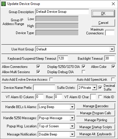
Group Description: This is a descriptive name for the Device Group, i.e.: “Shipping Department”.
Group IP Address Range: This is the range of device IP addresses for this group.
Device Type: This is the device type filter for this group. The combination of IP Range and Device Type are used to determine which devices will be a member of this device group. Leave this value blank to include all devices in the IP range, regardless of their Device Type.
StayLinked Server IP: Added in v15.2, this hidden/optional device type filter is typically used to split incoming connections between internal and external (internet) connections. Appearing in the space just below the device type, this area appears blank unless a special configuration option is enabled in the server configuration. This file is called espadmin.xml which can be found in the Config subdirectory of the StayLinked Server installation directory.
Manually edit the espadmin.xml file on your server to add the 'advanced_device_groups' setting to the administration node of the espadmin.xml file. You may need to close and then re-open your Administrator to receive the configuration when connecting to a server. Your espadmin.xml should contain a line similar to the following:
<administration advanced_device_groups="Y"/>
During a connection request, the Client reports the IP address to which it is attempting to connect. This value would typically be different if the connection is internal to a network than if it was coming in from an outside source. Along with other filters, this can help split incoming connections with highly randomized IP addressing.
Maximum Connections: This value will control the number of connections that are allowed to use this device group. (0 or blank = unlimited connections)
Host Group: This is the Host Group that defines which emulation hosts will be available to devices in this device group. If the selected host group is not available at the time a device connects, then the device will automatically use the ‘Default’ host group. A special host group named ‘Device Management Only’ is also available for selection. This host group will cause the device to run a Device Management Only session. There will be no Telnet or SSH access provided in this Device Management Only session. The client software will behave much differently on the device when the client is running a Device Management Only session. The ‘Device Management’ features have been end-of-life since September, 2015.
Keyboard/Suspend/Sleep Timeout: This value defines how many seconds of inactivity will pass before the device goes into sleep mode. A value of zero will cause the device to never timeout. This timeout requires that the ‘Application Lockdown’ Client Setting be enabled. The behavior of this timeout is device-dependent.
Backlight Timeout: Defines the number of seconds that the backlight will stay lit between keystrokes or scans on the device. A value of zero will cause the backlight to never timeout. This timeout requires that the ‘Application Lockdown’ Client Setting be enabled. The behavior of this timeout is device-dependent.
Allow Connections: This checkbox provides the administrator with the ability to determine which devices can establish sessions. This checkbox must be checked in order for devices belonging to this device group to be able to connect to a telnet session.
Allow Multi Sessions: This checkbox provides the ability to control which devices will be allowed to run Multi Sessions. This option will only have an effect if a Multi Session License is installed.
Display 5250/3270 OIA Area: Make sure that this checkbox is selected if you wish for the devices in this group to display the Operator Indicator Area at the bottom of the screen when running 5250 or 3270 sessions. The OIA looks like this: [ ][ ][ ][ ] and notifies you of Input Inhibit, Keyboard Lock, Message Waiting and Insert status. If all indicators were displayed, the area would look like this: [INH][LCK][MSG][INS]. For Version 14 Servers, you can select a ‘Graphical Operator Indicator Area’ for devices that support graphical elements. This option is configured in the ‘Telnet Host Entry’ by selecting the ‘Dynamic Screen Settings’ option under the ‘Manage’ menu.
Debug OIA: This option provides an enhanced OIA at the bottom of
the device display that shows the standard OIA indicators as well as
alpha/numeric field attributes, view port origin and the current cursor
position. The fully-populated Debug OIA looks like this: [ILM^A 01/001 01/001]
The Debug OIA generates much more network traffic as it is updated every time
the cursor is moved, so it should only be used to setup attributes like
‘Viewport Locking’ and Font Size settings.
Allow Color: For devices that are capable of displaying color screens, use this checkbox to control which devices will be allowed to display color. If this option is not checked, color-capable devices will display white text on a black background.
Auto Add DM License: Check this box to cause all DM-capable devices in this group to be automatically added to the Device Management database. Devices in this group will be added to the DM database only if the server is licensed for DM and if there are DM seats available to be issued to the device. (This option has been removed in v15.1 build 208 and newer.)
Auto Add Evolve Device Access: (v15.3) Check this box to cause all devices in this group to be assigned an Evolve Device license seat. Devices in this group will be assigned an Evolve License seat only if the server Evolve licensing available to be issued to the device.
Auto Add SpeechLink: Check this box to cause all SpeechLink-capable devices in this group to be assigned a SpeechLink license seat. Devices in this group will be assigned a SpeechLink License seat only if the server is licensed for SpeechLink and if there are SpeechLink seats available to be issued to the device.
Auto Add Speech: (removed in v15.3) Check this box to cause all Speech-capable devices in this group to be assigned a Speech license seat. Devices in this group will be assigned a Speech License seat only if the server is licensed for Speech and if there are Speech seats available to be issued to the device.
Device Name Prefix: The 5250 device descriptions for all RF devices falling within this device group IP address range will get this prefix. For each RF device in this device group, the name of the device description on the IBM i will be this Device Name Prefix followed by a unique suffix calculated based upon the IP address of the connecting device and the Suffix Octets and Decimal Suffix settings. If you leave this field blank, then device naming will not be enabled for this device group. If you wish to create a device name with no prefix, use the reserved prefix ‘NULL’ which will cause the system to generate a device name using only the suffix. The device name prefix can be any length up to 10 characters. If your configuration will cause a device name to be generated that is longer than 10 characters, you will be notified and a corrective measure will be suggested.
If you wish to manage your device names at the individual device, then you can specify [deviceid] as the Device Name Prefix and this will cause the client software to retrieve either the ‘Device Name’ from the PPC/CE.Net operating system, or use the ‘device_id’ client setting from the client INI file, and use that identifier as the entire ‘Device Name’.
Suffix Octets: The maximum size of the device suffix is 6 characters. This setting allows you to control the size of the device name suffix. If you select Decimal Suffix, then each decimal octet will require 3 positions and you can select 1 or two octets. If you de-select Decimal Suffix, then each octet will require 2 positions and you can select from 1 to 3 octets. You may select 0 octets only if the Low and High IP Address Range for the group are the same IP address.
Starting in v15.2, suffix octets can now be configured for public and private IP address use. Connections appear in the connections list with a hyphenated IP address are displaying an address reported by the Client and an address where the packets/connection came from. Workstation names built from IP address can use either the public or private address when creating these names. Public addresses are typically used only for NAT'd network connections.
Decimal Suffix: This option allows you to specify whether to use decimal or hexadecimal values to build the device name suffix.
Device Naming Examples:
- Device Name Prefix = SHP_
Suffix Octets = 3
Decimal Suffix = Unchecked
RF device IP 192.168.100.25 will be converted to IBM i Device Name SHP_A86419. - Device Name Prefix = SHP_
Suffix Octets = 2
Decimal Suffix = Checked
RF device IP 192.168.100.25 will be converted to IBM i Device Name SHP_100025. - Device Name Prefix = SHP_
Suffix Octets = 1
Decimal Suffix = Checked
RF device IP 192.168.100.25 will be converted to IBM i Device Name SHP_025. - Device Name Prefix = DEVICE0001
Suffix Octets = 0
Group IP Low Range = 192.168.100.25
Group IP High Range = 192.168.100.25
RF device IP 192.168.100.25 will be converted to IBM i Device Name DEVICE0001. - Device Name Prefix = NULL
Suffix Octets = 1
Decimal Suffix = Checked
RF device IP 192.168.100.25 will be converted to IBM i Device Name 025. - Device Name Prefix = [deviceid]
PPC/CE.Net Device Name = WHSDEV1
RF device IP 192.168.100.25 will use IBM i Device Name WHSDEV1.
VT Alarm ID Column: For VT sessions, you can specify the column where the VT Alarm ID Character will be found.
Row: For VT sessions, you can specify the row where the VT Alarm ID Character will be found.
VT Alarm ID Char: For VT sessions, you can specify a character, which when found in the location defined by the VT Alarm ID Column and Row, will cause the Alarm to be sounded on the device as specified in the ‘Handle Alarms’ setting.
Hide ID: For VT sessions, this setting will cause the VT Alarm ID Character to be hidden (non-visible) on the device.
Handle BELs & Alarms: You may select which type of audible indicator will be used when a 5250 display contains the ALARM DDS keyword or a VT BEL or VT Alarm ID is encountered. The options are None, Short Beep, Long Beep, Double Beep or Vibrate.
Handle 5250 Messages: You may select the method that will be used to display messages that appear on the message line 24 of the 5250 screen.
- Snap-To Message: This method emulates IBM’s Wireless Connect behavior causing the device window to snap down to the lower-left corner of the 5250 screen, allowing you to see the message. This method requires that you send a [RESET] key if the 5250 session keyboard becomes locked.
- Pop-Up Message: This method causes a pop-up message to be displayed that contains the entire text of the message. This method will automatically send a [RESET] key to unlock the 5250 keyboard when appropriate.
- Take No Action: Select this option if you want no action taken when messages appear.
- Popup Msg. Location: You may select the area on the device screen where system messages will be displayed. The choices are ‘Top’, ‘Center’ or ‘Bottom’ of the device screen. The default is to have system messages displayed at the ‘Top’ of the device screen.
Message Notification: You may select which type of audible indicator will be used when a new message appears on the message line. The options are None, Short Beep, Long Beep, Double Beep or Vibrate.
Manage Barcodes: Click this button to access a dialog that will allow you to configure barcode types for this device group.
Manage Program Calls: Click this button to access a dialog that will allow you to configure client-side program calls for this device group.
Manage Printing: Click this button to access a dialog that will allow you to configure client-side printing options for this device group.
Manage Startup Scripts: Click this button to access a dialog that will allow you to configure session start-up scripting options for this device group.
Manage Alt. Keyboards: Click this button to access a dialog that will allow you to assign alternate keyboard maps to be used by devices that are members of this group.
Managing Barcodes
For each device group, you may control the manner in which barcodes are scanned for that device group. The following window is presented when you click on the Manage Barcodes button on the Update Device Group window. The window contains some device group level barcode settings and a list of specific barcodes defined for this device group.
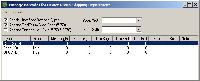
Enable Undefined Barcodes: This option works in conjunction with the list of barcode types that are configured for this device group. Check this box if you want to allow the device to scan barcode types that are not specifically configured for this device group.
Append Field Exit to Short Scan (5250): For 5250 sessions, select this option to cause a Field Exit to be automatically appended to barcodes that are shorter than the field into which they are being scanned. This option is often used to enhance scanning into display fields that cause an automatic end-of-record advance via the CHECK(ER) display attribute. (This setting has no effect for 3270 or VT emulation).
Append Enter on Last Field (5250 & 3270): For 5250 and 3270 sessions, select this option to cause an Enter to be automatically appended to barcodes that are scanned into the last field on the current application screen. (This setting has no effect for VT emulation).
Barcode Scan Prefix: This feature provides for the definition of characters to be inserted as a prefix to the scanned data. Select from the Drop-down list, or key in your prefix characters. This setting will affect all barcode symbologies unless a specific prefix is defined for a specific symbology.
Barcode Scan Suffix: This feature provides for the definition of characters to be inserted as a suffix to the scanned data. Select from the Drop-down list, or key in your suffix characters. This setting will affect all barcode symbologies unless a specific suffix is defined for a specific symbology.
You may add, edit, and delete Barcode Type entries using the “Barcode” menu or by right clicking on a specific Barcode Type entry in the list. When adding or editing barcode types for this device group, the following window will be displayed.
This dialog allows you to configure specific settings for specific barcode symbologies and lengths. You can add more than one configuration for various lengths of a single symbology so long as the Minimum Length matches the Maximum Length and you do not already have a setting defined for the specific length. There can be only one setting for a symbology where the Minimum Length and the Maximum Length are different or are zero. Using these length settings, you can have different barcode settings for the same symbology where the barcode values have different lengths.
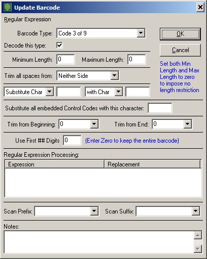
The following criteria are used to determine if the scanned barcode data will be affected by this particular barcode setting:
Barcode Type: Use this drop-down list to select the barcode type that you wish to define.
Minimum Length: Specifies the minimum value length to have this setting apply.
Maximum Length: Specifies the maximum value length to have this setting apply.
- Note: Input length restrictions for barcode types can be eliminated by setting both the Minimum and Maximum parameters to zero (0).
If the scanned barcode meets the criteria for this barcode setting, then you can control whether the scanned barcode is allowed to be processed using the following option:
Decode this type: Use this checkbox to enable the use of the scanned barcode in the session. If this option is checked, then the barcode is allowed, and the barcode data manipulation functions are applied. If this option is not checked, then the scanned barcode is rejected, and the device will beep.
For scanned barcodes that meet the criteria defining this barcode setting, the following barcode data manipulation functions will be applied in dialog order, from the top down:
- Trim all spaces from
- Substitutions
- Substitute embedded Control Codes
- Trim from Beginning/End
- Use First ### digits
- Regular Expressions
- Adding Scan Prefix and Suffix.
Trim all spaces from: This option determines how leading and trailing spaces in the barcode data will be handled. You can select to have spaces trimmed from neither side, the left side, the right side or both sides of the barcode data.
Substitute: This option allows you to specify a character or string within the barcode data to be replaced by a different character or string. Single character substitutions must be represented in the hexadecimal (0x00) format to differentiate them from string substitutions. To remove data, use [null] as the substitution string value or use 0x00 as the substitution character value.
Substitute all embedded Control Codes with this character: Allows you to specify a character to be used as a substitute for all control codes that are embedded in the barcode data. Control Codes are defined as characters with values less than 0x20. This substitution character must be represented in the hex (0x##) format. Enter a value of 0x00 to remove all control codes from the barcode data.
Trim from Beginning: Specifies the number of characters to trim from the beginning of the scanned data. Type in the number of characters to trim, or select the option to trim ‘to fit field’ which will trim characters from the beginning when the barcode data is longer than the field length.
Trim from End: Specifies the number of characters to trim from the end of the scanned data. Type in the number of characters to trim, or select the option to trim ‘to fit field’ which will trim characters from the end when the barcode data is longer than the field length.
Use First ## Digits: Specifies the number of characters from the beginning of the scanned data to use. This value is evaluated after the ‘Trim’ attributes have been applied. Set this value to Zero (0) to cause all of the remaining barcode data to be used.
Regular Expression Processing: Provides the ability to use sophisticated ‘Regular Expression Processing’ to manipulate barcode data. You can enter one or more ‘Expressions’ that are evaluated against the barcode data. If an expression matches the scanned barcode data, then the ‘Substitution’ will be processed against the barcode data. Regular Expression Processing for barcode data is covered in detail in the ‘StayLinked Barcode Regular Expression User Guide’.
Scan Prefix: Specifies the characters to be inserted as a prefix to the scanned data. Select from the Drop-down list, or key in your prefix characters. This setting will override the device group level setting for this specific barcode symbology.
Scan Suffix: Specifies the characters to be inserted as a suffix to the scanned data. Select from the Drop-down list, or key in your suffix characters. This setting will override the device group level setting for this specific barcode symbology.
Notes: This is a convenience field that has no effect on barcode
processing. It can, however, help you to organize and manage your barcode rules
by providing a place to record why you created this symbology-specific barcode
rule for future reference.
Managing Program Calls
For each device group, you may define up to three client-side program calls that can be mapped to specific keys on your device keyboard. The following window is presented when you click on the Manage Program Calls button on the Update Device Group window. The programs that are defined in this dialog must be installed on the individual devices. These program calls are often used for printing barcodes and other functions that must be processed on the device.
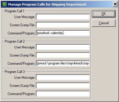
User Message: This parameter allows you to display a message on the device screen during the time that the client-side program is running. If you leave this parameter blank, then no message is displayed.
Screen Dump File: This parameter gives you the option of dumping an image of the entire current 5250 screen to a text file on the read/write drive on the device. The file will be written to the device before the client-side program is called. Do not specify a drive letter with the file name, as the StayLinked client determines what drive is available for writing, depending upon the device make and model. If you leave this parameter blank, then no screen image is written to the device.
Command/Program: This parameter specifies the DOS command or client-side program that is to be called. If the program does not exist, no action will be taken, and no error message is displayed. When the program has completed its processing, the session continues normally.
Managing Printing
For each device group, you may configure a group of settings that define how the server will identify and handle client-side printing for devices that belong to that device group. For VT Telnet Hosts, StayLinked supports the standard VT printing pass-through escape sequences.
Additionally, StayLinked provides a facility by which printer commands can be communicated to the device by reading the printer commands from a special application display screen and transmitting those commands to the device. This special application display screen is designed by the end user and is integrated into the end-user application. When this screen is displayed and identified by the StayLinked Server, the printer commands embedded in the screen will be extracted and delivered to the device where they will be transmitted to the printer via the selected COM port settings.
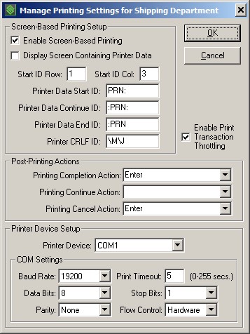
Enable Screen-based Printing: This option will enable or disable client-side printing for this device group for host applications where screen recognition is required.
Display the Screen Containing Printer Data: This parameter determines whether or not the screen, which has been identified as containing printer command, is displayed on the device.
Enable Print Transaction Throttling: Forces acknowledgments for each printer data packet sent. It is recommended to select this option for labels or documents that contain a large amount of printer instructions.
Start ID Row: This option defines the display row where the server will look for the Print Data Start ID and the Print Data Continue ID.
Start ID Column: This option defines the display column where the server will look for the Print Data Start ID and the Print Data Continue ID. This value is not included in the extracted printer data.
Print Data Start ID: This option describes the string of characters that, when found at the Start ID Column and Row, identifies this screen as containing a new set of printer commands.
Print Data Continue ID: This option describes the string of characters that will notify the StayLinked Server that more printing data is to be expected on subsequent screens. This ID should be used at the end of a screen when there will be more data displayed on the next screen. This ID should also be positioned at the Start ID Column and Row of the next screen that contains additional printer commands. This ID would be used when the printing commands are too complex to fit on a single application display screen.
Print Data End ID: This option describes the string of characters that will identify the end of the printer commands. When this ID is encountered, all of the collected printer data will be transmitted to the device. This value is not included in the extracted printer data.
Print CRLF ID: This option describes the string of characters that will identify the CRLF indicators on this screen. The CRLF indicators that are found in the extracted printer data will be replaced with an actual carriage return/line feed sequence when that data is transmitted to the device.
Printing Completion Action: This option controls how the server will respond when the printer attached to the device has successfully processed the printer commands. The action defined here will be sent to the printing command screen. For instance, if the printer completes printing, the Enter key can be sent to the screen to cause the printer command screen to be dismissed.
Printing Continue Action: This option controls how the server will respond when a screen of printer data is ended with a Printing Continue ID. This action would be used to trigger the display of the next screen that contains the additional printer commands.
Printing Cancel Action: This option controls how the server will respond when the printer attached to the device fails to process the printer commands. If you cancel the printing operation on the device, then this action will be sent to the printing command screen. For instance, if you cancel printing, the F12 key can be sent to the screen to cause the printer command screen to be dismissed. The value selected for these three actions will depend upon how the end user application has been programmed.
Printer Device: This setting configures the StayLinked client to support Serial COM communications with printer devices. If you wish to use RF or Bluetooth communication protocols, you will need to configure ‘Client Settings’ for the StayLinked client to support your printer. In the ‘Printing’ group of Client Settings, you will find the ‘Printer Type’ setting where you can choose ‘Generic RF’ or ‘Generic Bluetooth’ printers. Plus, there are some additional ‘RF Printer’ settings available.
Baud Rate: This option describes the Baud Rate of the printer connected to the device.
Data Bits: This option describes the Data Bits setting of the printer connected to the device.
Parity: This option describes the Parity setting of the printer connected to the device.
Print Timeout: This option defines how long the StayLinked client will wait for responses from the attached printer device.
Stop Bits: This option describes the Stop Bits setting of the printer connected to the device.
Flow Control: This option describes the Flow Control setting of the printer connected to the device.
Managing Startup Scripts
For each device group, you may define a startup script for each type of emulation available. The startup script will be processed only when a new session is established. The script will not be run when a device reconnects to an existing session. The script will always be processed against the first host screen that is presented to the device, typically a logon screen.
Each script can be up to 255 characters in length. Each script can contain any combination of characters and emulation mnemonic keywords. Emulation mnemonic keywords are contained within square brackets []. You can select mnemonic keywords from the ‘Insert mnemonic’ drop-down list, causing the selected mnemonic to be automatically inserted at the current cursor location within the script textbox. Startup Scripts should be carefully designed to function appropriately for the type of emulation, targeted host and end-user application. Syntax errors in the script will not cause errors, but could cause some part of your script to be ignored by the emulation host.
The following window is presented when you click on the Manage Startup Scripts button on the Update Device Group window. The example 5250 Startup Script below is designed to be processed against a 5250 logon screen. You profile ‘myuserid’ will be automatically typed into the first field on the screen and then the ‘Field Exit’ mnemonic will be processed, moving the cursor to the next field on the logon screen. Then, the password ‘mypasswd’ will be typed into the current field and an ‘Enter’ key mnemonic will be processed. This script would cause a user to be automatically signed onto the target IBM I emulation host.
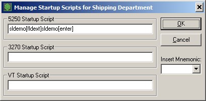
5250 Startup Script: Enter the startup script to be used when connecting to a 5250 Telnet host.
3270 Startup Script: Enter the startup script to be used when connecting to a 3270 Telnet host.
VT Startup Script: Enter the startup script to be used when connecting to a VT Telnet host.
Managing Alternate Keyboard Maps
For each device group, you can override the keyboard map that a device would normally use and specify a different keyboard map to be used as an alternate.
Keyboard maps are used by the StayLinked system as a cross-reference between the many and varied device keyboards and the various host types (5250, 3270, and VT). With StayLinked, you can use the default keyboard map or alter it to suit the specific needs of your device users and their applications. In addition, you can create alternate keyboard maps to support variations needed for a specific group of devices.
The following window is presented when you click on the Manage Alt. Keyboards button on the Update Device Group window.
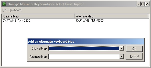
In this example, when an Intermec CK71 Windows Mobile 6, Alpha-Numeric keypad device connects to this Host, the alternate keyboard map for the Intermec CK71 Windows Mobile 6, Numeric keypad device will be used instead.
You may add and delete these alternate keyboard maps using the Keyboard menu (the Add New Alternate Map selection window is shown above). The Original Map and Alternate Map dropdowns provide a list of available keyboard maps from which to choose.
In case you are using Custom Device Types for your devices and you want to map them to an existing standard keyboard map, you may select the special value ‘** Enter a Custom Device Type **’ as the ‘Original Map’. Then select the desired existing ‘Alternate Map’. When you click OK, you will be prompted for a ‘Custom Device Type’ value that will be used for the ‘Original Map’ value.
Select “Save Changes” from the “File” drop-down menu to save any changes that you have made to the currently selected host group.
Share the post "Administrator User Guide – Device Group Administration"