Implementation Steps
The following steps can be taken to implement a SmartTE environment in your installation. These steps will vary based on the design and implementation of your host application. Examples of how these settings should appear to your devices have been included to help demonstrate these features. This document is intended as a quick overview of implementation, and contains only the most basic options and features.
The following is a general overview of the steps to enable graphical features:
- Create a tap spot collection for your application
- Select your telnet host entry
- Assign the tap spot collection to your telnet host entry
- Enable your dynamic settings in the host entry
- Test, tune and expand
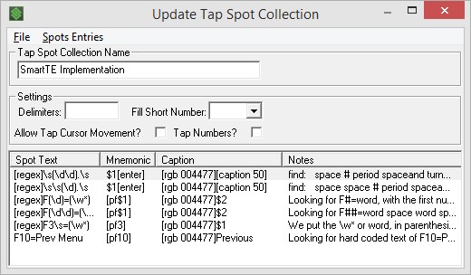
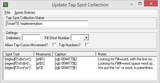
Create a Tap Spot Collection
Tap spots have been a part of StayLinked since nearly the beginning. With SmartTE, tap spots have been upgraded to allow regular expressions. These expressions allow the StayLinked Server to watch screen text for patterns, instead of being limited to static text elements.
At this stage, your tap spot collection may contain only one static line as a placeholder. You simply want to create a collection that you can start to work with and assign it to your host entry in the next step.
The key indicator that your collection is for use with SmartTE is that it should not have any delimiters. The static mappings still work the way they used to, but each tap spot collection can include both static mappings and regular expressions. Regular expressions are noted with the [regex] mnemonic. More information on regular expressions can be found in the regular expressions guide, or using various internet sources.
Some of the common expressions that are used for tap spot collections may include the following:
| \d | A numerical digit |
| \s | A space |
| | | This is an ‘or’ statement |
| (contents) for $# | Capture argument of contents for use as a $ variable |
| [caption #] | Create a label of the next # of characters |
| [caption #,#] | Create a label starting at the first number position thru the next # of characters such as |
| \w* | Word or collection of uninterrupted letters |
Select your Telnet Host Entry
StayLinked connections fall into a device group. Each device group points to a telnet host group, which is a list of telnet servers that will be available to that connection. Each telnet host in the group has its own configuration for screen recognition and dynamic settings. You can create a new entry or use an existing one, but any host group that contains more than one host entry will present the users with a choice.
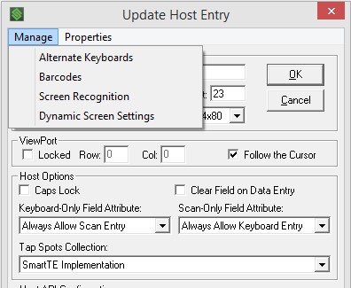
Assign your Tap Spot Collection to the Telnet Host Entry
Once you have your telnet host, select the ‘Tap Spots Collection’ that was created in the previous step from the pulldown menu.
Enable Dynamic SmartTE Features
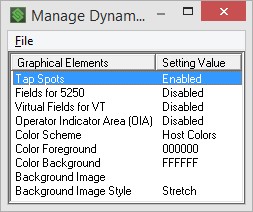
When you’re ready to try out the graphical tap spots, open your telnet host entry and select the Manage pull-down menu. Select Dynamic Screen Settings and you’ll get the dialogue as it appears here. Double click on Tap Spots and select Yes to enable the graphical version of your tap spots.
Other options can be enabled or disabled from this dialogue. If you select a background image, be sure to review the appendix section on image file paths. Devices that cannot retrieve the file will not be able to display it as a background.
As a note, the OIA setting will not affect VT emulation sessions.
Test, Tune and Expand
Once your basic settings can be tested and operate on your client, you can expand your tap spot collections or enable additional options in the Dynamic Setting panel.
This expansion of options is demonstrated in the following section, which starts with basic configuration and then expands to capture additional content.
Screens that do not easily conform to dynamic rules can be manually reformatted using screen recognition.
Sample Implementation
This demonstration begins after creating the telnet host entry and enabling the graphical tap spots. This section is essentially the demonstration of step 5 from the previous section, testing and adjusting the configuration to get our desired results.
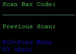
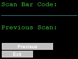
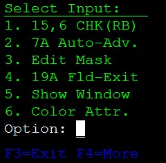
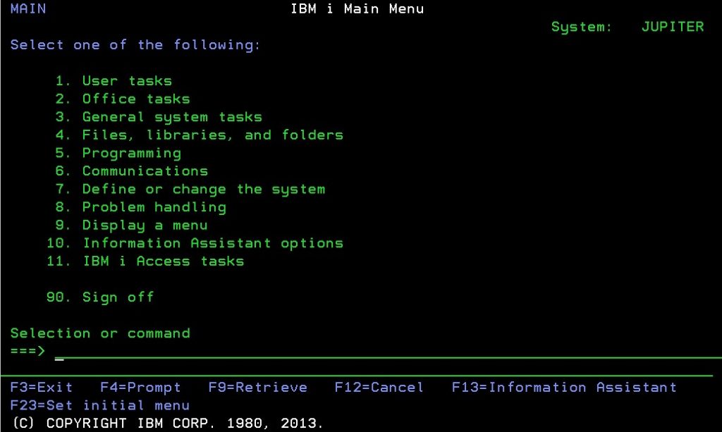
Starting with a basic emulation screen, you would want to identify patterns or commands on the screen that you might want to turn into buttons. In this screen, there are two commands immediately apparent, the F10 and F3. They’re a bit hard to see in the dark blue, so turning into buttons will help make them more obvious.
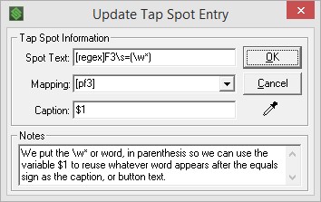
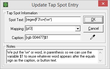
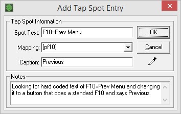
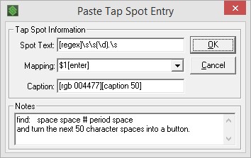
There are two ways to approach this. The first would be to create a static tap spot and the second would be a regular expression. We’ll use the F10 as a sample of fixed, and a regular expression for the F3. Adding these expressions to the tap spot collection (see the notes for details):

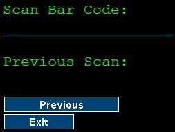
After a disconnect and reconnect to resend the client screen, the emulation screen now looks like so:
The default light grey buttons may make the text hard to read, so adding a color code to the caption provides a higher contrast. In this case, [rgb 004477]:
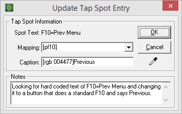
This shows that the buttons are applied, until I return to the previous screen. Notice the F3 button doesn’t get created. Looking at the entry in more detail, the answer should stand out. This expression looks for the letter F and the number three, then a space and equal sign. On this screen, there is no space between the three and equals.
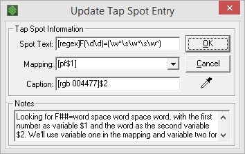
In this case, I’ll create a single expression that looks for the F, then a number, an equals and a word. Since this will affect several functions, we’ll put both the beginning and end parts in parenthesis so we can use them as variables. Here’s the expression (below) with the results to the right.
Be sure to avoid overlapping entries. Screen items that meet multiple regex entries will create multiple overlapping buttons. Each button will work, but will send more information to the client and may not paint properly. In this example, there are now two different arguments that would affect the F10 key if it is mapped to Prev Menu. Removing the original entry for F10 will prevent this conflict.
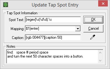
So far, this works great until I come across a screen with a two-digit function key and three word title. I’ll copy my previous entry for single-digit functions, but add another \d for the second function key digit. I’ll also add another space \s and word \w* for each possible word in the button description.
This means that my function keys have all been customized with a standard set of four rules, including the original entry that was a slightly different format.
Adding two more expressions makes a significant difference in the display of this standard IBMi 5250 screen.
Notice the first expression looks for two initial spaces. As part of the expression, the spaces become part of the button and then both the single and double digit menu items will line up together.
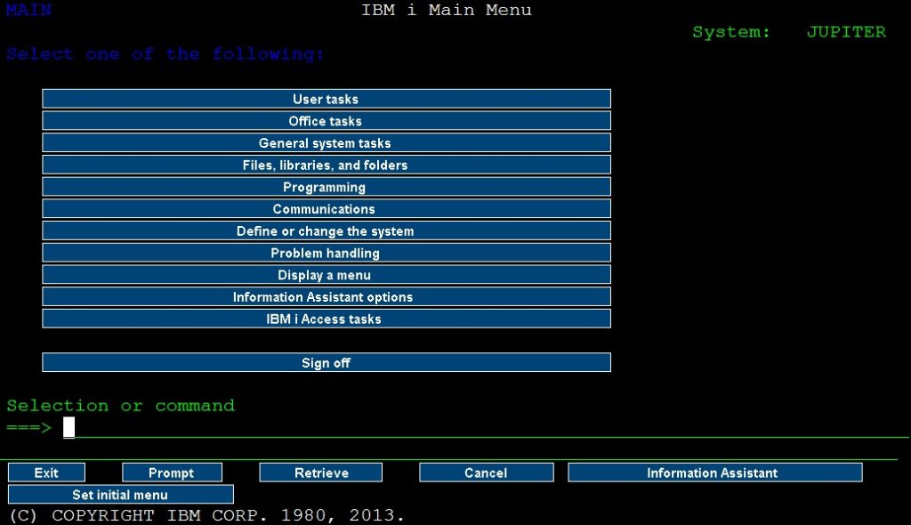
An IBM Client Access screen:
The new expressions for the numeric items are found at the bottom of the previous page. The function keys follow the previous examples in the sample application.
The Dynamically Created SmartTE Screen:
In this example, the caption is configured for 50 characters. This would need to be tested among other screens, since a menu with two columns may land within the 50-character configuration.
It may be beneficial to create a flow chart of each screen in order to validate that each is tested with your dynamic configuration.
Share the post "Implementing Dynamic SmartTE Steps"