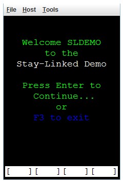
The following is a quick demonstration of the SmartTE reformatting features applied to a simple telnet screen. Each step and alternative options are described in more detail in the respective section of the Administrator.
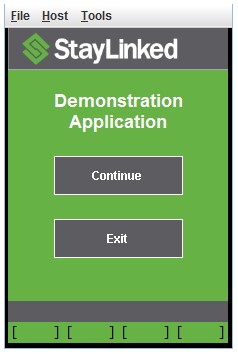
Taking this screen Creating this screen
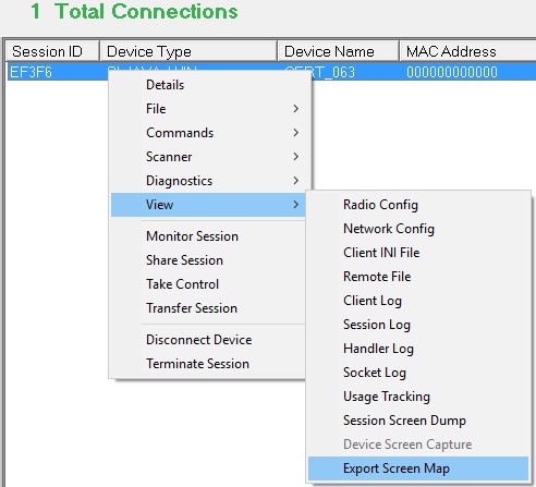
The first step is to capture a screen map. Screen maps are a snapshot of the screen you’re looking for. Using a StayLinked client, connect to the server and navigate to the desired screen. Once on the screen, use the Administrator’s Connections list to identify the device. Right click the session and select View > Export Screen Map. Give the map a name to save it to your library of screen maps.
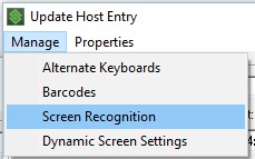
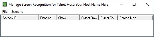
Open your telnet host entry. If you’re not sure which entry to use, check the device group to see which host group is being used. You can see connections ‘by device group’, right click a device and select Details, or by double clicking a connection to see the connection details. From the host entry, select the Manage pulldown menu and Screen Recognition.
Right click in the list of Managed Screens to add a new entry:
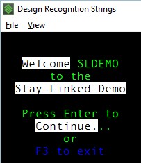
Name your new entry, and then right click in the recognition strings to select the screen objects that make this screen unique. If no screen map has been selected, a dialogue will appear and then prompt you to select the screen map that identifies this screen recognition event. Once the screen map opens, select enough display items to make this event unique.
When the screen map is closed, the recognition page will display a list of the screen elements you have selected.
Now that the screen will be recognized, you can use the various other tabs to perform your desired actions. In this case, we’ll use the Screen Designer tab to create a new reformatted screen. Select the tab, then right click in the list box to add a new entry. The entry will prompt for the screen dimensions that will use this new reformatting. The connection details dialogue mentioned above is a good place to see the screen size in rows and columns. The standard OIA (brackets along the base of the emulation screen) will consume a display row when enabled, so add one row if the device group includes the OIA. The Graphical OIA configured in the dynamic features does not consume a row of emulation space.
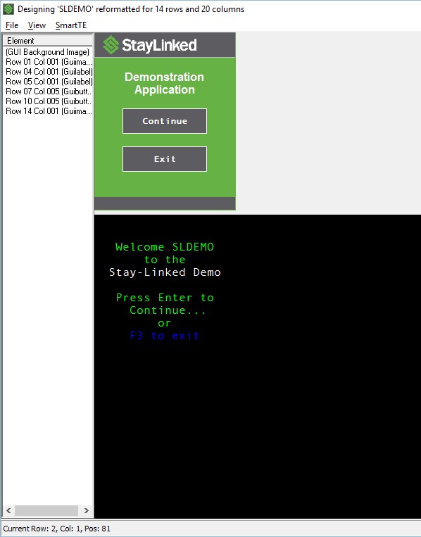
In this example, the screen is set to 15×20, but the emulation space is 14×20 because of the OIA. Once the new entry at 14×20 is created, the designer will display the screen map and new display area in a new window. The example to the right has been slightly trimmed for article space.
From here, we can start to add new elements.
Each screen below shows an element being added and then the new display of what the screen would look like.
This example uses a total of 7 elements to reformat the display space. In this example, none of the original screen contents are directly added to the net display. Each of the new elements are a graphical display object used in SmartTE.
The first element is a ‘graphical background color’, which is added in the graphical image dialogue. Select the file pulldown from the top of the dialogue and then set background > graphical image. Rather than an actual image, you can use the color picker to select a background color:
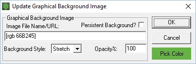
This simply sets the background to green. The color picker allows you to enter RGB values, or select from carious color options.
The second element added is the StayLinked banner across the top of the screen. This example selected an image that has the grey background with the logo on the left edge, setting the image to left alignment, but stretch to fit the area height of two rows and the entire 20 columns wide of the display area:

The third element is a simple label to paint the word Demonstration on the screen:

In this example, the width is set for the entire screen, but the alignment is set to centered, allowing the device to position the word in the center of the screen regardless of the device display size.
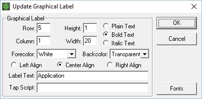
The fourth element is an identical label, but with the word application below the previous label:
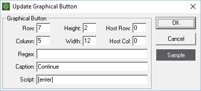
The fifth element is a continue button, allowing the user to quickly and easily proceed:
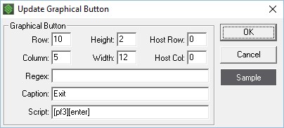
The sixth element is a cancel button. This button is similar to the previous button, except that it is positioned lower, has a different caption, and performs a different script when pressed.
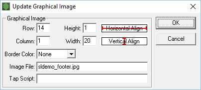
The last element is a simple graphical image that sets a color banner along the bottom of the screen to help outline the work area.
Instructional Video – Example of Screen Designer Features
Share the post "Screen Reformatting Example"